A pre-TAB project review is the first step to a successful project. The rewards of a pre-TAB review are well worth the 3% of project time spent on the review. Missing dampers, undersized ductwork, undersized terminal units, incomplete control sequences and incorrect airflow directions are but a few of the conditions noted in a pre-TAB review. The time saved identifying problems before the start of test and balance is extremely valuable compared to problems surfacing at the end of a project when time is compressed.
“Before anything else, preparation is the key to success.”
– Alexander Graham Bell
What are Shell Spaces?
One problem that may be identified is the use of “shell spaces” in a project: areas in the project that are designed for future occupancy but are “shelled” or unoccupied during original project construction. These spaces are designed with minimum ventilation for construction cost and energy savings but air handling units (AHU) serving these areas are designed for maximum capacity.

Design Challenges in Healthcare Facilities
Many of the new medical facilities being constructed will be designed for MRIs or ORs to occupy an entire floor. For reasons unknown to the TAB contractor, only 25% of the space is built out during the initial construction with plans to build out the remainder of the floor or shelled areas later, sometimes before the original project construction has been completed. In several instances, the project engineer is given a particular use for a floor with expected load for design purposes and in the middle of the project, the Owner changes their mind and repurposes the usage of the floor which may drastically change the space load requirements. For one reason or another, an AHU system may end up overdesigned or designed for more airflow than required for the area served.
Overdesigned AHU systems operate at a lower airflow and a lower total static pressure, but the static may not be low enough to keep the system out of fan stall. Even with a reduction in static, the operating point may be in the fan stall region of the curve. The static pressure will decrease as the airflow velocity decreases, but one often overlooked condition is that the connected terminal units will likely require the same system static pressure whether there is one terminal or fifty. It has also been noted that to keep construction costs to a minimum, terminal units are designed at or slightly above their maximum inlet velocity. In this case, when the project engineer is alerted that terminal inlet velocities exceed 2000 FPM during a project review, many times the reply is that the manufacturer maximum is 2500 FPM or higher. What the manufacturer is able to achieve in the factory with perfect conditions is seldom reproduced on a construction project.
Optimizing Air Handling Units to Operate at Partial Capacity
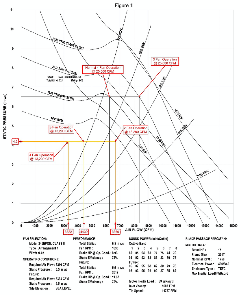
On a recent hospital project, while reviewing the project documents, it was noted that one AHU was selected for an area completely built out but in reality, half of the area was shell space. The AHU was equipped with four centrifugal airfoil plenum fans designed to operate at 6250 CFM each for a combined flow of 25,000 CFM at 6.5” total static pressure. The AHU was scheduled for fans at N+1, three fans could operate at 8333 CFM to maintain 25,000 CFM if one fan is disabled. When the project plans were reviewed, the total plan airflow had been reduced from 25,000 CFM to 13,290 CFM. Figure 1 fan curve details the design fan operation for normal operation at 6250 CFM per fan and three fan operation at 8333 CFM per fan. It should be noted that the selection point for normal four fan operation is in an area where fan stall is experienced. Although it is on the right side of the stall zone, fan stall was noted at times when the fan selection point was at or above any point horizontally on the fan curve in the stall zone.
Actual measured conditions were 13290 CFM at 3.45” TSP. With four fans in operation at the plan airflow of 3,322 CFM per fan (13,290 AHU CFM), fan stall was apparent by AHU vibration. One fan was disabled resulting in three fans operating at 4,430 CFM per fan, and operation was smoother than with four fans, but fan stall remained. Figure 1 displays the operating point for four, three and two fan operation at 13,290 CFM at 4.2” total static pressure. Four fan operation is clearly in an area where fan selection is discouraged, the three fan operation point is slightly in the fan stall region while two fan operation is acceptable.
The AHU fans are installed with backdraft dampers and when a fan is disabled, the disabled fan will be isolated from the operating fans. The remaining fans will increase speed to meet the system design static pressure setpoint. It was fortunate that a fan array was selected instead of a single fan; it would have been a major undertaking to modify the system or AHU to provide a safe, efficient operating system designed for 25,000 CFM at 6.5” but supplying 13,290 CFM at 4.2” total static pressure.
The temporary fix was simple, disable two of the AHU fans. More effort was required to determine in what state the system was to be set. Turn off two fan motor VFDs? Alter the sequence of operation? Command two fans off in the BAS and reference a note that the fans are not to be enabled? We have seen all three options. The project Owner decided to instruct the plant operators to manually cycle two fans every week. In either case, the Owner must be aware of the conditions of operation and have input as to what state the temporary condition should be set.
Early detection that a problem existed provided time to consult with the engineer and determine if immediate action was necessary. It was determined that this condition was temporary and that the AHU was equipped with multiple fans, so there were options available. We did not know at what static pressure the system would be operating at the reduced airflow, but with the availability of multiple fans and the increased range of fan RPM due to the N+1 fan requirement, the engineer was confident that the AHU performance would be acceptable at the reduced airflow. Much less stressful than determining there was an issue while balancing the hospital critical care area at the end of the project just prior to occupancy.
Written by Terry Wright, TBE